


Automated Systems for LPG and Petroleum Products Loading and Metering
Automated Systems for LPG Loadingand Metering
Automated systems for Loading and Metering (ASLM) of LPG and petroleum products are designed for automated 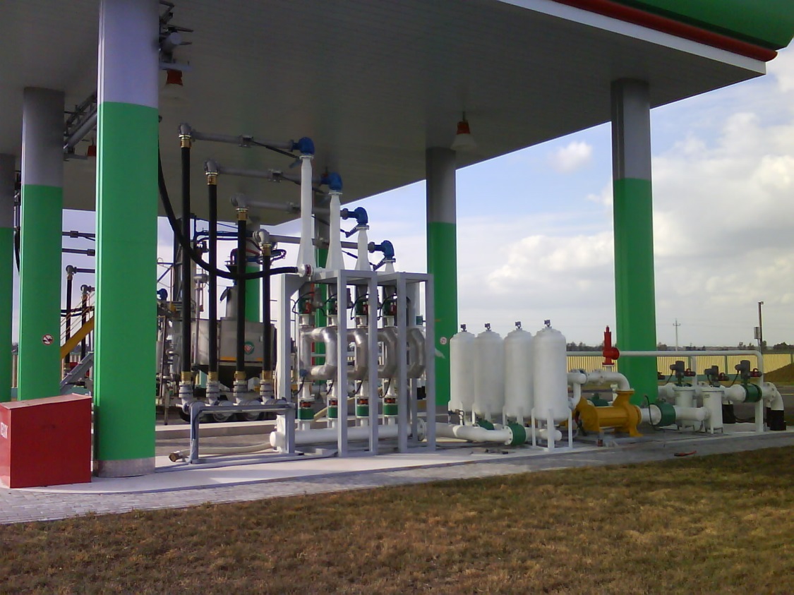 loading/unloading and metering of the product by mass and volume.
ASLMs are used at the tank loading facilities for loading tank trucks and railcars with petroleum products.
ASLM design utilizes Oil loading package design as a basis.
Automation and Custody transfer system is based on Instrumentation and Control system Potok, registered at State Register of Measuring Equipment of the RF as a single package.
The systems are installed within Oil loading packages manufactured according to TUBY 100420390.004-2014 and certified to TR CU 010/2011 (Certificate No ТСRUC-BY.NO01.00002).
Oil loading packages are designed for explosion proof application.
VRF controller installed in the package is connected to Operator Workstation via Modbus RTU (RS-485) interface.
Loading packagesКН-1 are assigned to climatic category У, placement category 2, and operating temperature range from -40 to +40 °С.
Process solutions implemented within package design are aimed at meeting the following challenges:
- Provide maximum accuracy of oil and petroleum products measurement;
- Provide Document processing automation and bаlance sheet producing;
- Ensure Occupational Health and Safety regulations compliance;
- Ensure Environmental Protection from petroleum products exposure while Loading/unloading operations.
Loading/unloadingoperations.
Components of AutomationandCustodytransfersystembasedonInstrumentation and Control system Potok
|
Description |
Quantity |
|
Top loading arm assembly: - swivel DN 100, spring-mounted; - vacuum breaker valve to assist loading arm discharge; - telescopic drop pipe ; - overfill protection sensor; - drop pipeparking position switch; - STOP button; - vapor recovery hoseDN50; - removable drip bucket |
1 |
|
Intake module assembly: - pump type and availability as perprojectspecification; - manually operated ball valveDN 100; - vacuum pressure gage; - filter(gas filter separator), mesh size 100µm; - pressuresafety relief valve |
1 |
|
Access ladder |
1 |
|
Structural steel(Skid base) and piping |
1 |
|
Service platform |
1 |
|
Dropdown walkway |
1 |
|
Shutoffsolenoidvalve, NC, SENS, DN 80 (for top and bottom loading) |
2 |
|
Bottom loading equipment DN 100assembly: - bottomloadingarmDN 100 c/w parking lock; - manually operated ball valveDN 80; - vaporrecoveryhoseDN 50; - communicationcabletoconnect overfill protection sensors withAPI coupler |
1 |
|
Junction Boxes, cabling |
1 |
|
Instrumentation and Control system Potok assembly: - VRFFlowcomputer, explosion proof; - MicroMotionF-300 mass flowmeter (accuracy class 0,15%); - gage pressure transmitter (accuracy class 0,5%); 4-20 mA; - temperature transmitter (error0,5 °С); 4-20 mA; - drop down walkway(stairs)parking position switch (24V); - ESD button (24V); - grounding control deviceУЗА-220В-БП-БЗ; - Loading Operator Workstation software– 1 off(license) per facility |
2 |
|
Standard Documentationtobesuppliedwitheachloadingpackage:
|
1 |
Note:
Should scope of supply cover installation of two oil loading systems within one loading bay scope of supply may comprisedrop down walk way.

Petroleum Loading Terminal
Main system components
Top loading arm
Top loading arm is designed to fill tank trucks with increasing flowrate to avoid static generation at the drop pipe end. Top loading arm comprises:
- swivels DN 100, spring-mounted;
- telescopic drop pipe (complete with ESD station);
- overfill protection sensor;
- vacuum breaker valve to assist loading arm drainage;
- removable drip bucket;
- vapor recovery hose.
Swivel DN 100 serves drop pipe positioning purpose and places telescopic drop pipe into tank truck filler neck. It also maintains product delivery from top point to bottom of the tank without product losses. Swivel joints are designed to ensure connection and rotation of the articulated arm spools both vertically and horizontally.
Top loading arm is an articulated connection consisting of two couplings and drop pipe interconnected by swivel joints.
Parking position switch prevents cantilever from swinging.
It also prevents drop pipe from being pushed out of the tank truck by high flow.
Buffer spring ensures smooth swivel and drop pipe move while placing drop pipe into tank truck filler neck.
Buffer spring is a housed balancing mechanism that consists of a number of springs installed on the axis.
The mechanism balances equipment independent of couplings and drop pipe inclination angle.
Telescopic drop pipe is made of aluminum alloys and available in two versions: sealed (for vapor recovery arms) and unsealed (for arms without vapor recovery).
Telescopic (sealed) drop pipe is equipped with vapor recovery cone, complete with outside oil and petrol resistant rubber seal, to ensure sealed loading. Vapor recovery while loading is maintained via coupling to fit vapor recovery hose from tank truck. Recovered harmful vapors (volatile organic compounds) may be delivered through flame arrester either back to tank when recovery procedure is on or to flare.
Drop pipe is a telescopic device that seals pipe internals with its rubber sealing when hold closed. Drop pipe is pushed out by gravity. (Unified design is ensured by groove coupling rings rotation against disk seal with 6 rollers. The cap is also equipped with a coupling to fix vapor recovery hose and overfill protection sensor coupling).
Vapor recovery hose is made of polyurethane mixture, inside diameter 50 mm.
Removable drip bucket is designed to avoid oil residue running-off outside surface of a drop pipe.
Overfill protection sensor installed on top loading arm allows for transmission of signal when permissible tank truck filling level is exceeded.
Overfill protection sensor is designed to shut off loading automatically if operator has set the doze exceeding the permissible level excluding driver or operator intervention. Overfill protection sensor is a vibrating probe VEGASWIG 63 type.
Vacuum breaker valve installed on the top point of loading arm provides for quick and complete discharge of its moving parts from petroleum products into tank truck. Vacuum breaker valve is normally closed. When loading is complete (minimum 5 seconds after) the valve opens under the influence ofdepression created by petroleum product in the drop pipe.
Vapor recovery hose DN 50 (for top loading) is made of polyurethane mixture (or petrol-resistant rubber) to carry vapors outside the loading package boundaries.
Optionally vapor recover hose may be equipped with flame arrester and vapor return valve.
Vapor return valve is designed to prevent backflow of vapors. Vapor return valve delivers vapors only in one direction. When direction changes to the opposite the valve closes, shutting off any vapor circulation.
Shutoff solenoid valve
Packages are equipped with two shutoff valves designed to control flowrate while top or bottom loading.
Shutoff solenoid valve is designed to shut flow off after set petroleum doze has been loaded and to ensure exact flow control at minimum rate not exceeding 10m3/h at the start and at the end of loading such doze. If required, system can be adjusted to maximum flowrate as well as to volume when package converts to small rate via system software and to maintain smooth flowrate regulation through rpm control of the pump.
Shutoff solenoid valvetogetherwithpumpVRFcontrollerensureprogrammableautomatictanktruckloadingprocess and stabilization of nominal product flowrate under changing loading conditions (tank innage level and etc.) that contributes to a better instruments and dozing accuracy.
Shut-off solenoid valve is a two-way solenoid valve.
Two-way solenoid valve is designed to ensure fluid and gas flow control in piping via two bores: main and auxiliary one.
Bottom loading equipment
Bottom loading equipment consists of:
- bottom loading arm, DN 100 complete with API 1004 coupler;
- Manually operated ball valve;
- Vapor recovery hose,DN 50;
- Overfill protection sensors communication cable.
Loading package utilizes HEFA bottom loading arm DN100 (Czech Republic) or analogs manufactured by Magna Engineering to ensure sealed loading.
Arms are equipped with API dry break couplings.
Vapor recovery hose equipped with flame arresters is also available upon request.
Flame arrester, installed downstream of vapor recovery hose, is designed to stop propagation of flame into oil and petroleum tanks on a temporary basis if explosive event has occurred.
Supplementary component of bottom loading equipment is overfilling protection cable complete with a plug for connection with tank truck socket. While VRF controller maintains overfill protection.
Intake Module
Intake module consists of:
- Pump, capacity 100m3/h. Any type available, as per project specification;
- Manually operated ball valve to shut off product supply if required;
- Compensator (if applicable) – to reduce pump vibrations against metering unit;
- vacuum pressure gage;
- Gas filter separator or HEFA filter, mesh size 100µm;
- Pressure safety relief valve.
Gas filter Separator is utilized to separate and purge gas- air mixture from hydraulics system.
Together with gas separation the flow is subjected to filter strainer, consisting of separate disks with screen, mesh size up to 0,1mm. Filter design allows for complete dismantling and assembly on site that contributes to significant reduction of cleaning and maintenance duration and thus to reduction of equipment downtime. Filter strainer ensures two stages of filtration.
Automated System for loading and metering
Automation and Custody transfer system is based on Instrumentation and Control system Potok.Single System assembly comprises complete set of Loading package instruments.
Instrumentation system is based on mass flowmeter and VRF controller that ensure dozing and custody transfer of the product with accuracy no less than 0,15 % by mass and volume, as well as fuel density measurement with accuracy no less than 1,0 kg/m3.
Loading packages КН utilize VRF-Exd controller for flowrate calculation and dozing. VRF controller comprises:
-local control station;
-local display.
VRF controller ensures automatic tank truck loading and whilst as follows:
- flowrate regulation to maintain «step loading»;
- unloaded doze metering with relative error:
- by unloaded petroleum mass - ±0,15%;
- by total unloaded petroleum volume reduced +15°С - ±0,2%;
- doze increment;
- by volume – 1 l;
- by mass – 1 kg;
- Receiving signals from pressure and temperature transmitters;
- Pump unit control;
- Receiving signals from position switches, grounding device;
- Vapor recovery system connection (if applicable).
Indication of fuel unloading results and information on unloaded batch in liters, kilograms and fuel density is maintained on an integrated display.
Installation of local three-line large-sized display to indicate loading process of each product is optional.
Metering system is peculiar for the following integrated functions:
- Calculation of volume reduced by temperature both to 15°С and to 20°С;
- Dozing control of additives and coloring agents by VRF controller complete with metrological certification of dozing system;
- VRF controller memory storage of fiscal archives considering loading operations and information output to the reporting documents;
- Autonomous operation from local control station, located onsite.
Local specialized VRF dozing controller is equipped with integrated keyboard and display per each point of loading.
Keyboard allows for loading doze set up directly onsite utilizing software identification – user password.
VRF controller maintains fiscal data storage considering the loading operations, able to connect with upper level system, point-of-sale control system (to be selected by Customer)and Customer identification system.
Customer identification system may be connected to the controller via digital protocol.
Customer identification system is designed to prevent unauthorized loading andexport against forged Power of Attorney.
Identification system (optional) is based on proximity switches utilizing RFID technology. The latter contributes to expansion of logistics functions of control systems due to introduction of optimization and reengineering of transportation processes.
However, extra efficiency is achieved due to an opportunity to build up integrated functional structure, introduction of complex automation solutions and improvement of cost system, service level increase and reduction of order-to-delivery cycle.
Proximity switch ensures two operating modes – «passive» and «active», passive case sends information, read from the label, upon the request from server; active case во initiates data submission to certain host straight after label identification.
Magna Engineering suggests transport identification to be maintained via labelling transport with RFID–chip and ID card issue to driver on the entrance to Oil delivery terminal.
Proximity switch connects to VRF controller and regulates fiscal loading processes.
Metering system Potok complete with operator workstation (optional) make automated loading control system.
Operator workstation shall display digital and graphic information (graphic panels, trends). Operator workstation interface is maintained in the Russian language. Operator software implements all process, blocking and security control functions.
Magna Engineering has successfully integrated Automated Process Control System into Automated Company Control System.
System is equipped with Uninterruptible Power Source (UPS) integrated in hardware/software package (HSP) scope of supply.
Power supply of upper level hardware and software (HSP), sufficient for trouble free equipment shutdown, is maintained from UPS with battery back up (no less than 30 min). Power supply of UPS data is maintained from AC power source, 220V, 50 Hz DC, or two independent AC 220V, 50 Hz.
Automated petroleum products truck loading control system ensures integration with Automated Process Control System of Oil Delivery Terminal.
System provides for station control systems integration into Automated Process Control System of Oil Delivery Terminal in order to obtain information on the unloaded product amount, units performance control via local network Modbus protocol.
Manufacturer introduces Modbus interface address space layout.
There is a physical connection between Automated loading control system and Automated Process Control System of Oil Delivery Terminal maintained with Ethernet and TCP/IP.
Micro Motion F-300 Mass flowmeter
Mass flowmeter provides precision mass flow measurement of fluid travelling through it by mass and volume with – maximum permissible relative error of 0,15%.
Mass flowmeter and VRF controller are connected via digital network protocol.
Gage pressure transmitter
Gage pressure transmitter is installed on the header downstream of mass flowmeter and used for pressure regulation within the flowline.
Output signal (4-20 mA) is delivered to analog input of VRF controller.
Temperature transmitter.
Temperature transmitter is installed on the header downstream of the mass flow meter and is designed to control temperature of pouring oil-product.
Output signal (4-20 mA) is delivered to the analog input of VRF controller.
VRF controller
In order to maintain energy saving and "smooth start" Variable Frequency drive controlled by VRF controller is used to feed petroleum product.
VRFcontrollertogetherwithShutoffsolenoidvalveensureprogrammableautomatictanktruckloadingprocess and stabilization of nominal product flowrate under changing loading conditions (tank innage level and etc.) that contributes to a better instruments and dozing accuracy.
Grounding control device
Grounding control device ensures reliable grounding conductor-to-tank truck connection via threshold current measurement within external intrinsically safe circuit of the grounding cable with galvanic isolation. Grounding module transmits status data on internal channel processor module, which, in accordance with the algorithm of ASLM control program, gives command to power module to start or finish loading.
Structural Steel
Access ladder is a steel staircase with 450slope and horizontal rungs complete with grating and fencing.
Skid base and piping.
Skid base is a steel structure consisting of base, loading arm parking position stand post, anti-slip grating and fencing.
Service platform is a steel skid-mounted structure complete with grating and fencing.
Dropdown walkway is designed for overpassing from process racks to tank trucks and railcars. Dropdown walkway is a steel structure consisting of stairs and parallel motion mechanism to keep the stairs in a horizontal position. Buffer spring serves the purpose of balancing mechanism for dropdown walkway.
Handrails protect the operator from falling. Rubbing parts of the walkway, as well as the tank truck contact spools are made of spark-proof materials.
Control and power box
Power box is designed for power supply and electronic instruments wiring up as well as for ASLM systems emergency protection. Power box Circuit Diagram is submitted with as-built documentation package.
Power box maintains startup and shutdown of electric pump units (electric drives) with control signal (~220V) via magnetic controllers, ensures control signal blocking and power surge protection. Power box also ensures toll operation power supply and automation (if applicable), power supply of system controllers, UPS, grounding control devices.
Junction boxes, cabling
Junction boxes are skid-mounted. They are used for installation of solenoid actuated valves.
Cabling is maintained with flexible metal hoses or trays.

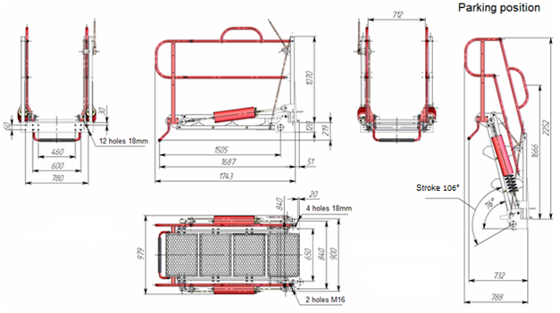
Loading package КН. Overall and coupling dimensions.
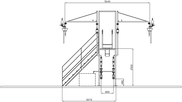
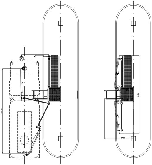
Loading package КН. Overall and loading dimensions